According to the manual sheet you should just push the extender section to the bottom for 6m (50 MHz) but this did not work for me. Using a NanoVNA I could find a workable configuration for both 6m (50 MHz) and 4m (70 MHz) bands.
For both bands I only used only one base pin (instead of two for HF), the coil pushed down to it’s lowest position and the tuning was done using the telescopic top part. The telescopic top part was extended partly:
6m
8 sections of the top part extended, top part length 79 cm
4m
2.5 sections of the top part extended, top part length 28 cm
If anyone has a better take on tuning on these bands please let me know 🙂 I have just tuned on SWR, no clue what the radiation pattern might be. Also, note that these are measurements that worked for me. Check your SWR.
6m operation6m SWR4m operation4m SWR
https://media01.nerdia.net/uploads/2E471E05.png240320Stefan Helanderhttps://media01.nerdia.net/uploads/nerdia-logo-340x156.pngStefan Helander2025-07-20 14:02:452025-07-21 09:48:53Tuning the HF-P1 vertical antenna for 6m and 4m bands
To import a codeplug for Anytone AT-D878UV into the CPS for AT-D578UV or AT-D168UV, the only way is to export it to CSV from the AT-D878UV CPS and then import it. But for some strange reason, Anytone has decided to make the CSV formats slightly incompatible… Come on, Anytone. Why??? This bug/feature seems to be related to splitting Color Codes into RX and TX that was implemented in the 3.06 release of the CPS.
The import into the CPS for AT-D578UV or AT-D168UV will silently fail. No error message is displayed but upon investigation I discovered that the Color Codes for the DMR Channels were wrong (set to CC1 in all cases). I maintain a codeplug for AT-D878UV with almost 900 channels, so fixing this manually is not an option.
I use the latest CPS for all models, that is for AT-D878UV version 3.07, for AT-D578UV version 1.21 and for AT-D168UV version 1.06.
A workaround is to edit one of the column headers in the CSV file before importing. Which column depends if you are importing to AT-D578UV or AT-D168UV.
AT-D878UV -> AT-D578UV
Change “RX Color Code” to “Color Code”
AT-D878UV -> AT-D168UV
Change “TxCC” to “TxCc”
Anytone AT-D878UV to AT-890UV
If you open the RDT-file from an AT-D878UV into the CPS (version 1.01N in my case) for the AT-D890UV it will look fine but I discovered that channels randomly got the wrong TX CC in the AT-D890UV after doing this. Some settings in APRS get lost too but those can be edited manually. And the APRS TOCALL for AT-D890UV is APAT89.
So basically the RDT file from AT-D878UV can be opened and used in the AT-D890UV CPS but the file Channels.CSV must be edited and then imported into AT-890UV CPS.
This is how I solved it.
I use LibreOffice to manipulate CSV-files. Excel will probably work too.
Export Channels.CSV from the AT-D890UV cps. The content is not important, we will only need the header line from this file.
Export Channels.CSV from the AT-D878UV. I assume these are the channels you want into your brand new 890.
Open the Channels.CSV from the AT-D890UV and copy the first line (header line).
Open the Channels.CSV from the AT-D878UV and replace the first line with the line you copied from the AT-D890UV file.
Go to the column with the “RX Color Code” header (in my case column U). Copy the content from the entire column except the header.
Scroll right to the column with the “txcc” header (in my case column BY at the far right). Paste the content below the header cell.
Save the edited Channels.CSV file from the AT-D878UV and go to Import in the AT-D890UV CPS and import only the Channels.CSV file.
This way you will get all TX CC the same as RX CC.
If you have found more incompabilities that needs to be handled, please let me know and I will add it to the article.
https://media01.nerdia.net/uploads/nerdia-logo-340x156.png00Stefan Helanderhttps://media01.nerdia.net/uploads/nerdia-logo-340x156.pngStefan Helander2025-05-08 07:55:282025-12-20 06:13:16Importing an Anytone AT-D878UV codeplug into AT-D578UV, AT-D168UV or AT-890UV
When I got my first Anytone AT-D878UV in 2019 the roaming function used to display which channel it had roamed onto but later on, probably after a firmware upgrade this disappeared rendering the roaming function rather useless.
This continued even though I switched to the latest AT-D878UVII Plus. I recently asked a friend who also got the latest model if he had the same problem – which he hadn’t.
This made me suspect that this is an error that had occurred in my codeplug and continued to exist even though I’ve switching models (since the RDT-files are upward compatible I didn’t bother to make a new codeplug for the new radio, so I just opened the RDT-file from the old one).
So I exported everyting on my current codeplug to CSV-files, went into the CPS and made a new codeplug, imported the CSV files and walked through Optional settings to set up everyting as I wanted. Then wrote the new codeplug to the radio and guess what – now it displays the channel it is roaming on!
This is my wishlist for features / fixes for the Anytone AT-D878UV and AT-D587UV DMR radios. Comments, additions and suggestions are welcome, contact me on sm0rgm@helander.se. Maybe the Anytone people will read it 😉 I will submit it through my dealer as well, for them to forward to the Anytone developers.
In the analog APRS message, add the possibility to enter a code which will be replaced by the radio’s current frequency, mode etc so people who sees my APRS packet knows what frequency I am listening on, for example %QRV1 will be replaced by the frequency, mode etc receiver 1 is set to. And %QRV2 will be the corresponding for receiver 2 in my radio. For example, if receiver 1 is set to 434.650 MHz DMR, CC04, TS2 the analog APRS will become “434.650 CC01 TS2”. And if it is set to for example 145.600 MHz FM it would become “145.600 FM”.
Make APRS Voice Alert work. The problem is that CTCSS filtering is done before AX.25 APRS decoding. Turn them around, so AX.25 APRS decoding is done before CTCSS filtering. Doing that, Voice Alert would work well on the Anytone since you can select no CTCSS for the APRS transmission but select CTCSS, both TX and RX for the APRS monitoring channel, which also will be used when you press PTT to make a voice alert. (Today, if I set CTCSS RX filter to 136.5 Hz in europe or 100 Hz in US, no APRS will be received at all.)
Scanning. When scanning and the scan stops on a channel with traffic, it would be very nice if the radio stayed on that channel when pressing exit to stop scan. Now it goes back the the channel that was selected when scanning started and I have to manually go to the channel with traffic. Also a quick press on the PTT should stop the scanning on the current channel.
Roaming. Please bring back so the radio displays which channel it is roaming on. This was the case in early firmwares but disappeared, so now it just displays the channel that was selected when roaming was started. Which means that on a roaming channel, I have no idea which repeater I am using or even which band I am transmitting on. Useless! I know there was a problem if there were more than one channel in the roaming zone with the same freqency, CC etc, the first one in the list matching was displayed even if it was the wrong one. Still, this is better than now knowing at all.
There is actually no such thing as “analog” APRS. The traditional APRS over AX.25 on 144.800 MHz (or 145.390 MHz in other parts of the word) is actually defined as a digital mode.
However, Anytone has a possibility in their radios choose wether to send APRS over AX.25 or as position data over the DMR channel. This settings can be found in MENU -> APRS -> Upload Type, “A -Aprs” for APRS over AX.25 or “D – Aprs” for using the DMR. In Anytone they call these modes “Analog APRS” and “Digital APRS”.
APRS over AX.25 – “analog” APRS
In this mode positions are transmitted on a simplex channel (144.800 MHz in IARU region 1) and can be received by anyone in range. The packets can be repeated by digitpeaters (WIDE1 for local “fill in” digitpeaters and WIDE2 for wide coverage digipeaters). If the packet hits a digitpeater with an I-gate it is transported into the APRS-IS system and can be seen in aprs.fi.
The traditional APRS over AX.25 packet radio has many more functions than just position reporting, such as telemetry, weather reports, messaging etc etc. If your radio is capable of receiving APRS you can also see other hams in the area (position, distance, direction etc).
APRS over DMR – “digital” APRS
In this mode, the radio uses the built in function in the DMR specfication to transmit position data. When this position data reaches the Brandmeister servers it is converted to APRS and fed into the APRS-IS system and can be seen on aprs.fi.
APRS over DMR is limited to only position data so if your goal is to just show up on aprs.fi, this can be the mode of choice for you. You miss out on all other features of APRS when using DMR or “digital” APRS.
If you look at the APRS menu on the Anytone for example, the APRS SMS function is only availible for “Analog APRS”.
APRS SMS not availible in “Digital APRS” (over DMR)
For me, I choose the “old school” APRS over AX.25 all days in the week 🙂
https://media01.nerdia.net/uploads/analog_vs_digital_aprs.png2881081Stefan Helanderhttps://media01.nerdia.net/uploads/nerdia-logo-340x156.pngStefan Helander2023-07-02 10:23:192023-07-02 10:28:27Analog vs digital APRS
Looking at many how-to guides for the Anytone AT-D878UV / AT-D578UV and APRS, it can be hard to determine if APRS should be transmitted as FM (20 kHz bandwidth) or FM narrow (12 kHz bandwidth). Some guides show WIDE while others show NARROW.
The answer is clear in the IARU region 1 VHF band plan – APRS on 144.800 MHz should be transmitted using FM narrow.
https://media01.nerdia.net/uploads/nerdia-logo-340x156.png00Stefan Helanderhttps://media01.nerdia.net/uploads/nerdia-logo-340x156.pngStefan Helander2023-06-24 15:27:132023-06-24 15:27:14APRS (packet radio) – FM wide or FM narrow?
My analog APRS transmissions with the AT-D878UV was not received by any other stations. The problem was that when the codeplug is created (using New in the CPS), the values for Transmit delay and Prewave Time is set to 0 (zero) for APRS and this will not work (probably to battery saving as this is not a problem with the AT-D578UV for example, which will work with much lower values for Transmit Delay and Prewave Time).
Solution:
In the CPS -> APRS -> set Transmit Delay to 600 ms and Prewave time to 600 ms.
Anytone AT-D878UV analog APRS TX not working – solution
I’ve tried to find an explanation to these values online but haven’t found anything closer than “it controls the time after activating the transmitter until data is being sent”. So I tried setting each value, one at a time to it’s maximum and this is what I think it does:
Transmit Delay: The radio starts transmitting a packet but it sounds like it waits “Transmit Delay” milliseconds before it starts transmitting any valuebla data. During this time my guess it is filling the packet with zeroes.
Prewave Time: The radio pulls the PTT but waits “Prewave Time” milliseconds before it starts to send the packet. During this time, the radio just sends carrier.
If I set the Prewave Time too high, my receiver will not receive and decode the packet. I’ve experimented with values for Prewave Time with different values and between 80-600 ms it seems to be working.
https://media01.nerdia.net/uploads/anytone_at-d878uv_aprs.png202559Stefan Helanderhttps://media01.nerdia.net/uploads/nerdia-logo-340x156.pngStefan Helander2023-06-17 07:23:002023-06-24 10:29:22Anytone AT-D878UV analog APRS transmissions not working
This little APRS-tracker from the late 90’s or early 00’s is a neat little device, however pretty old. It uses an external GPS receiver (via RS232) and connects to a radio, like a HT for example.
According to the manual, the configuration utility runs under Windows 95 or 98 (yes, indeed old stuff). I have a TM-1 lying in a box collecting dust so I figured that I should fire it up and see if I could use it for something fun (today APRS is gaining some attention again since many new radios has analog APRS rx and tx build in, like the Anytones).
It turned out that it worked fine under Windows 10. I used an USB to RS232 adapter. In the device manager, find the COMx-port adapter, under Properties -> Port -> Advanced, I had to select COM1 to COM4 since the old software just supports these ports.
I installed it and right clicked on the program file for the TigerTrak configuration utility and selected Compatibility -> Win 95 (not shure if this is needed but I did it anyway).
To connect the TM-1 to the configuration utility, first start the utility. With the TM-1 connected to the serial port (straight cable), power it on while holding PWR and MODE simultaneusly. The software should indicate CONNECTED and the LOCK led on the TM-1 should go green.
As special path 1 i used WIDE1-1 and special path 2 WIDE2-2. This will cause packets received by a WIDE digitpeater to repeated two hops. If that is overkill (like in an urban area with many digipeaters) you could use WIDE2-1 to limit it to one WIDE hop instead.
Nowadays there is a specific TOCALL for TigerTrak units: APTIGR
https://media01.nerdia.net/uploads/IMG_20230604_130815.jpg14441926Stefan Helanderhttps://media01.nerdia.net/uploads/nerdia-logo-340x156.pngStefan Helander2023-06-15 18:53:432023-06-17 07:26:18TigerTronics TigerTrak TM-1 configuration under Windows 10
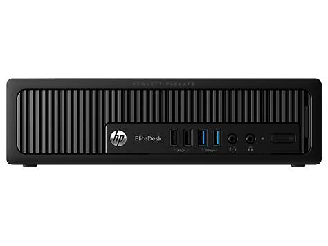
I got a HP EliteDesk 800 G1 USDT Ultra Slim Desktop computer for my ham schack. This is a small computer running on an external power supply just lika a laptop. It turned out to be the major source of RFI in my ham schack.
HP EliteDesk 800 G1 USDT
I suspected the power supply was the culrpit as those are switched ones and thought it might be possible to run the computer directly on my 13.8 VDC power supply that I use for my radios. The only voltages used in a computer is 12 and 5 volts, so there is probably a voltage regulator on the power input that regulates the voltage down from the 19 volts DC that the power supply outputs. Will it also run on 13.8 VDC?
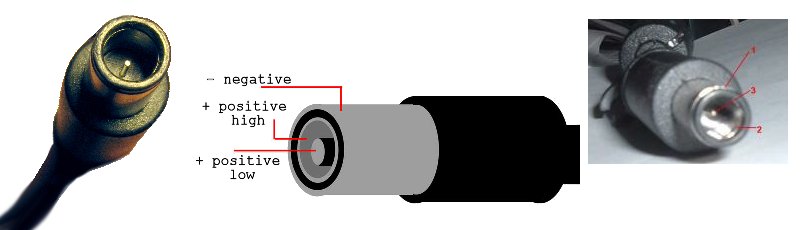
The power cable to the HP EliteDesk 800 G1 USDT has a 3 pole connector, just the same as on laptops. One is negative, one is positive and the pin in the middle is a “power good” signal from the power supply. I read about people running 3rd party power supplies by connecting the power good over a resistor to the positive side, see this page.
Will it run if I just connect the power good to positive without a resistor? When I measured the voltages from the original power supply positive was +19 VDC and power good read about +12 VDC so it might be sufficient. Discussing it with a tech savvy friend, he suggested it might work and be worth a try.
I didn’t want to cut the cable on the original power supply but luckily I have a friend who hoardes old technical stuff and he happened to have an old broken HP laptop power supply, with the correct cable (who saves broken power supplies?, well it turned out to be useful in this case)
It works!
It turned out it works fine, no resistor needed. This might vary from model to model, but the HP EliteDesk 800 G1 USDT it works by directly connecting power good to the positive. This (image below) is the cable I now use to run my computer directly on 13.8 VDC. Black lead is negative, white is positive and blue is power good.
On 20 meters (14 MHz) my noise floor dropped from S5 to S0-A1!
Power cable to run a HP EliteDesk 800 G1 directly on 13.8 volts DCIC-706 noise level on 20 m (14 MHz) when running computer directly on 13.8 VDC
https://media01.nerdia.net/uploads/IMG_20221103_173344-scaled.jpg25601920Stefan Helanderhttps://media01.nerdia.net/uploads/nerdia-logo-340x156.pngStefan Helander2022-11-05 10:31:112022-11-06 11:05:37Running HP EliteDesk 800 G1 USDT on 13.8 volts DC